 VIEW FULL SIZE ↗
01 / FLAT SCREEN
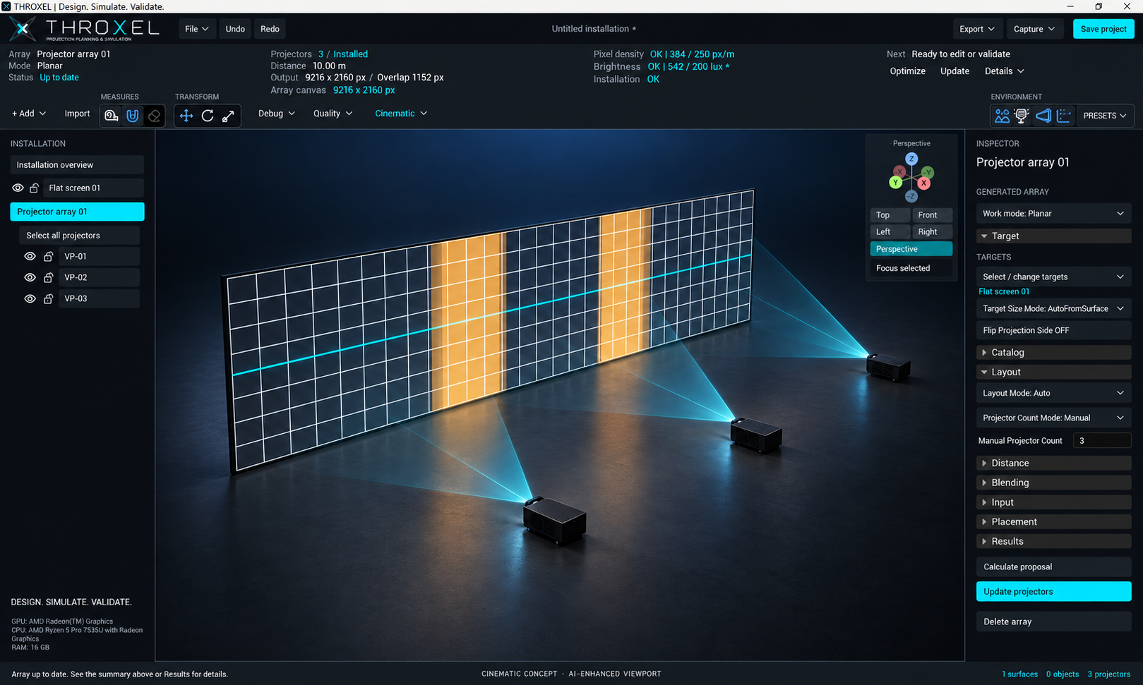
Three projectors. One panoramic canvas.
A planar blending concept with two overlap regions, shown inside the THROXEL workspace.
 Private beta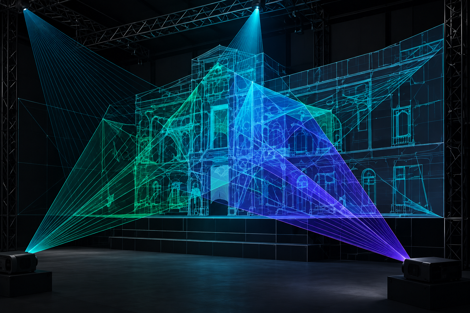
PROJECTION PLANNING & SIMULATION
A production tool for audiovisual professionals.
Plan the geometry. Explore the projection.
Make your decisions before going on site.
01 / SEE THE INSTALLATION
Move beyond a flat diagram. Explore the relationship between the projector, its beam and the projection surface inside a rendered 3D scene.
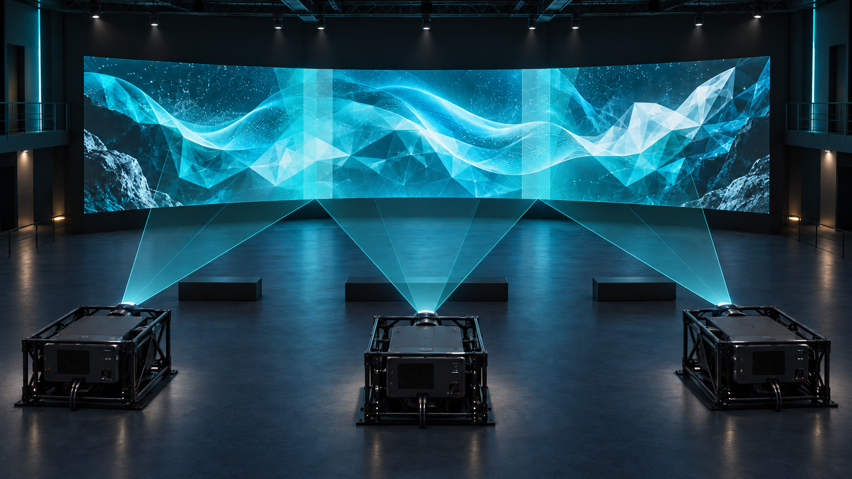
THROXEL brings visual simulation and projection calculations into the same workflow. Assess how the installation occupies the space, how the image reaches the surface and how multiple projectors work together.
EXPLORE THE WORKSPACE
Explore four installation concepts in the THROXEL interface. Select an image to see the scene and controls at full size.
Cinematic concepts · AI-enhanced visual mockups of the intended rendering finish. These are not unedited software captures or validated installation designs.
VIEW FULL SIZE ↗A planar blending concept with two overlap regions, shown inside the THROXEL workspace.
 VIEW FULL SIZE ↗
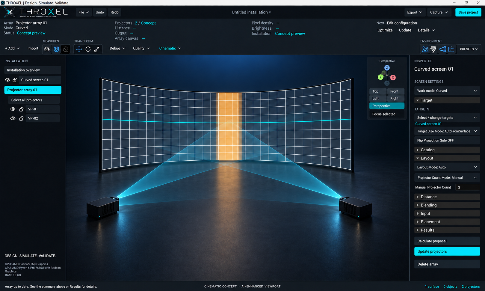
A curved-screen concept that makes the relationship between surface curvature, crossed beams and overlap visible.
 VIEW FULL SIZE ↗
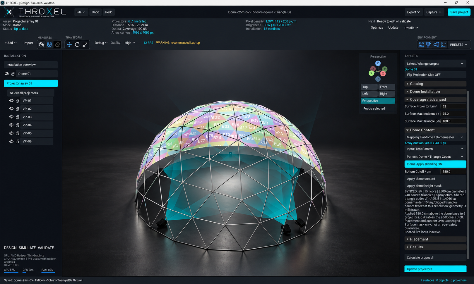
Based on a THROXEL scene: a 25 m dome, 5V frequency and 15 floors, with triangle-ID test patterns, white structure and work lighting. All six projectors sit at the perimeter: five cover the walls and the sixth tilts upward toward the ceiling.
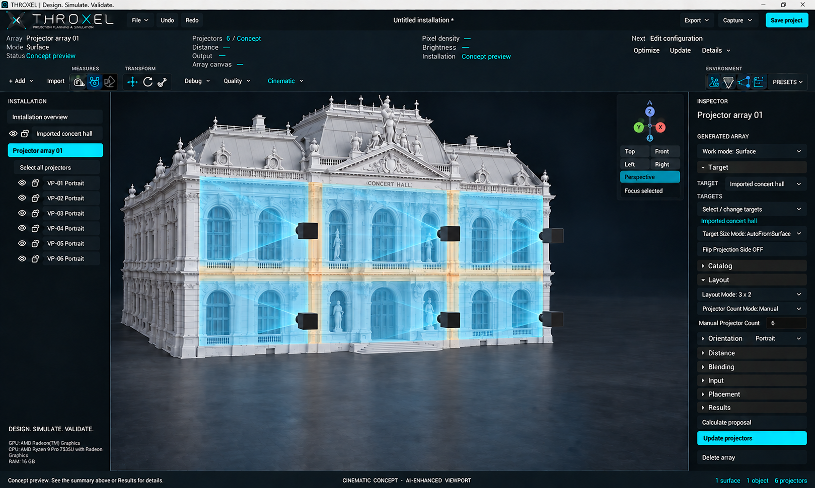 VIEW FULL SIZE ↗
A rectangular mapping area on the front facade, leaving the roof and upper sculptures unprojected. Six matching projector proxies form a 3 × 2 array, with each lens aligned to its region and soft translucent projection volumes.
02 / PROJECTOR & LENS CATALOGUE
A projection system occupies real space. THROXEL connects the optical specification with the physical equipment, so the installation can be planned around the hardware that will actually go on site.
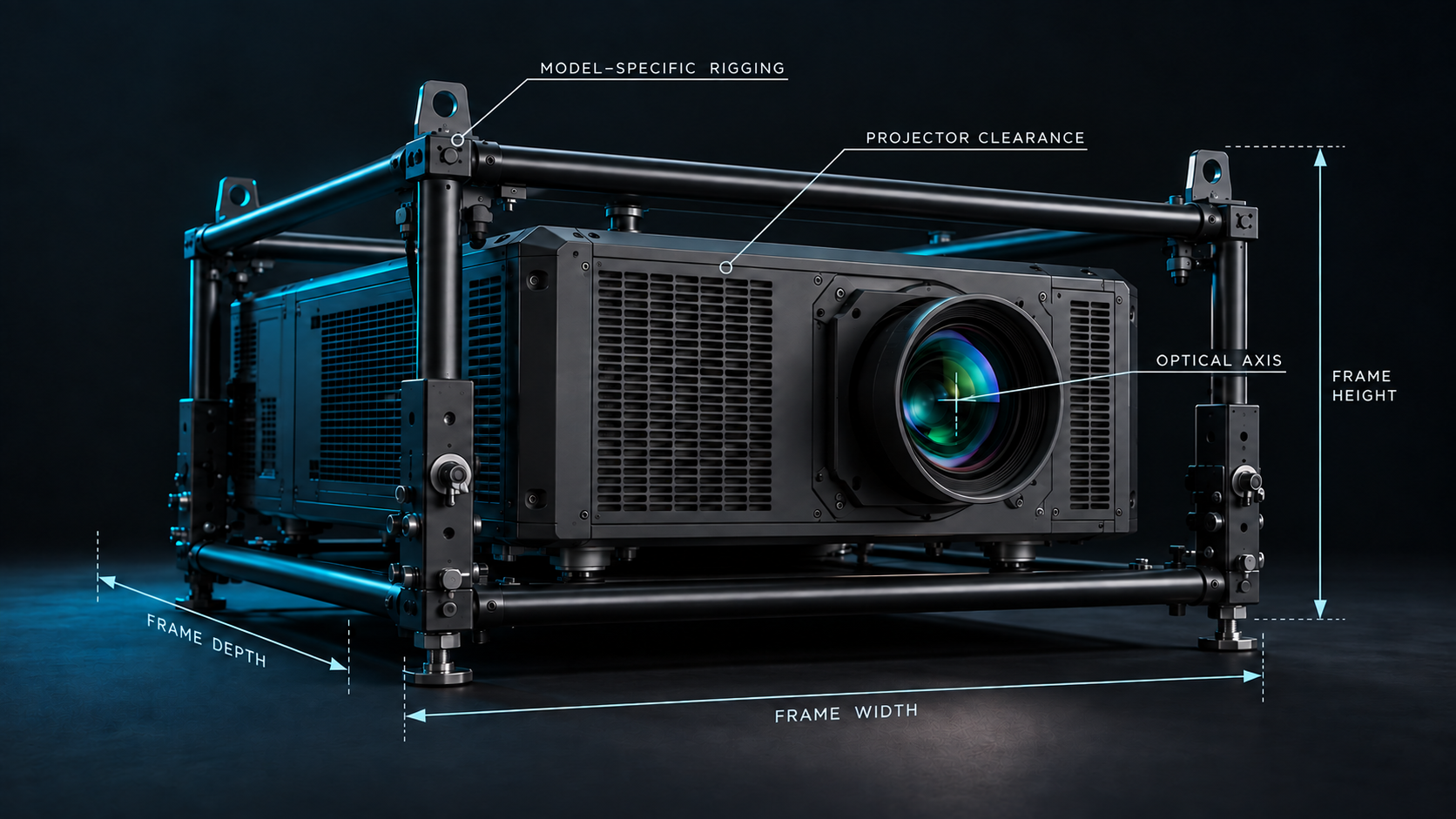
The catalogue brings together projector models, compatible lenses and manufacturer specifications. Projector dimensions and model-specific rigging-frame geometry give the optical calculation its physical context, wherever those profiles are available.
Lens ratio, resolution, optical origin and lens-shift limits all matter to a projection design. Lens-distortion visualization is also part of the planned workflow, using clearly identified visual approximations where measured lens data is unavailable.
Consider the complete equipment envelope, the lens position and the mounting frame alongside the projected image. The aim is to bring more real-world detail into the planning stage and reduce surprises during installation.
03 / ONE CONNECTED WORKFLOW
Execute without surprises.
Build the scene around your installation. Define flat or curved screens, position projectors and give every surface its place.
SPACE / SCREENS / PROJECTORSExplore projection in a 3D environment with real-time rendering. Review coverage, projector arrays and the overlap between images.
RENDERING / COVERAGE / BLENDINGReview the proposed installation and communicate its layout through technical diagrams and projector test patterns.
REVIEW / DOCUMENTATION / TEST PATTERNSBUILT-IN SURFACE GENERATOR
Create projection surfaces directly inside THROXEL. Start with the screen geometry, adjust it to the installation and use it as the target for your projector array.
Create a flat projection surface and set its dimensions and position in the scene. Use it to plan image coverage and multi-projector blending.
Build curved screens with adjustable geometry. Explore how the screen shape affects projector placement, coverage and the overlap between images.
The surface provides the geometric reference for the blend calculation and 3D simulation. Refine the screen, recalculate the array and review the resulting installation.
Use the Surface Generator to create screens within THROXEL, and imported 3D models to give the installation its architectural context.
AUTOMATIC BLEND CALCULATOR
Plan multi-projector coverage around the screen you need to fill. THROXEL brings the blend calculation into the 3D scene, so you can review the proposed installation in its spatial context.
Work with projector and lens selections, resolution, screen geometry and overlap requirements. Generate an array, inspect the coverage and refine the proposal.
Target geometry · Projector model · Lens · Resolution
Projection layout · Coverage · Blending regions
Inspect the result · Refine the setup · Prepare the technical export
TECHNICAL EXPORT
Turn the proposed setup into documentation that can travel beyond the 3D workspace. Give technicians and clients a shared view of the installation.
Export technical views showing projection surfaces, projector positions and projection geometry. Use PNG and PDF outputs to support installation planning and project discussions.
Bring projector and lens information together with the distances, image dimensions, resolution and overlap data associated with the planned system.
Generate and export test patterns for individual projectors, with identification and blending references to support the installation workflow.
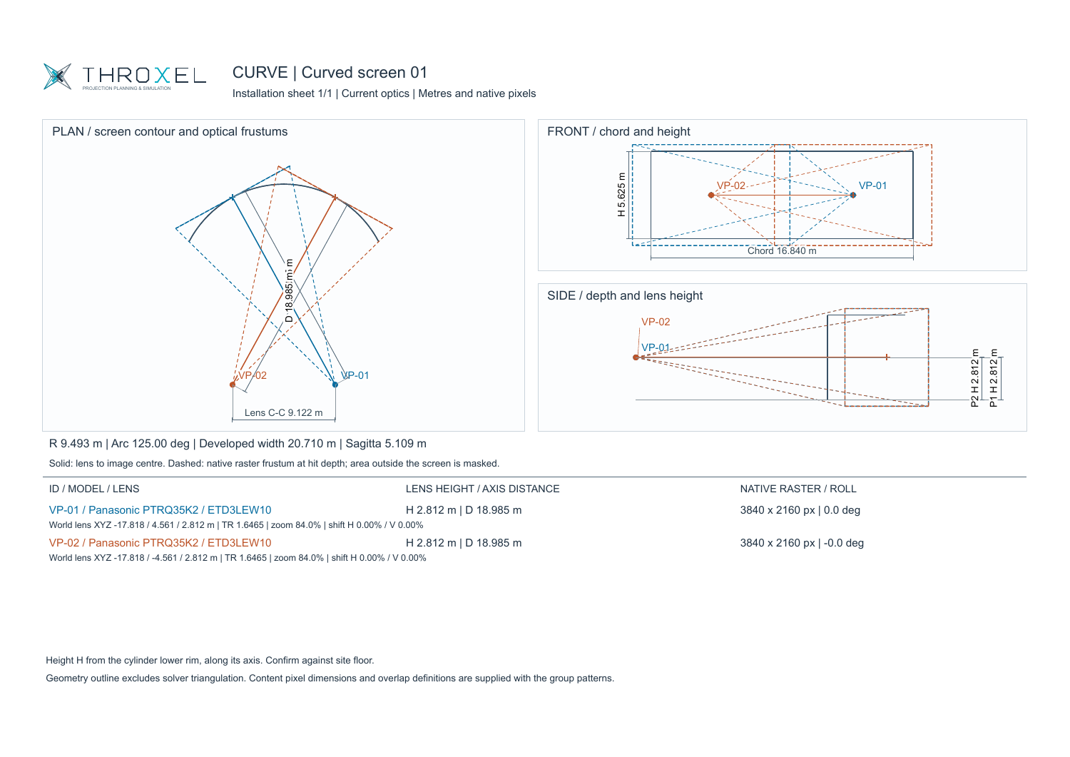
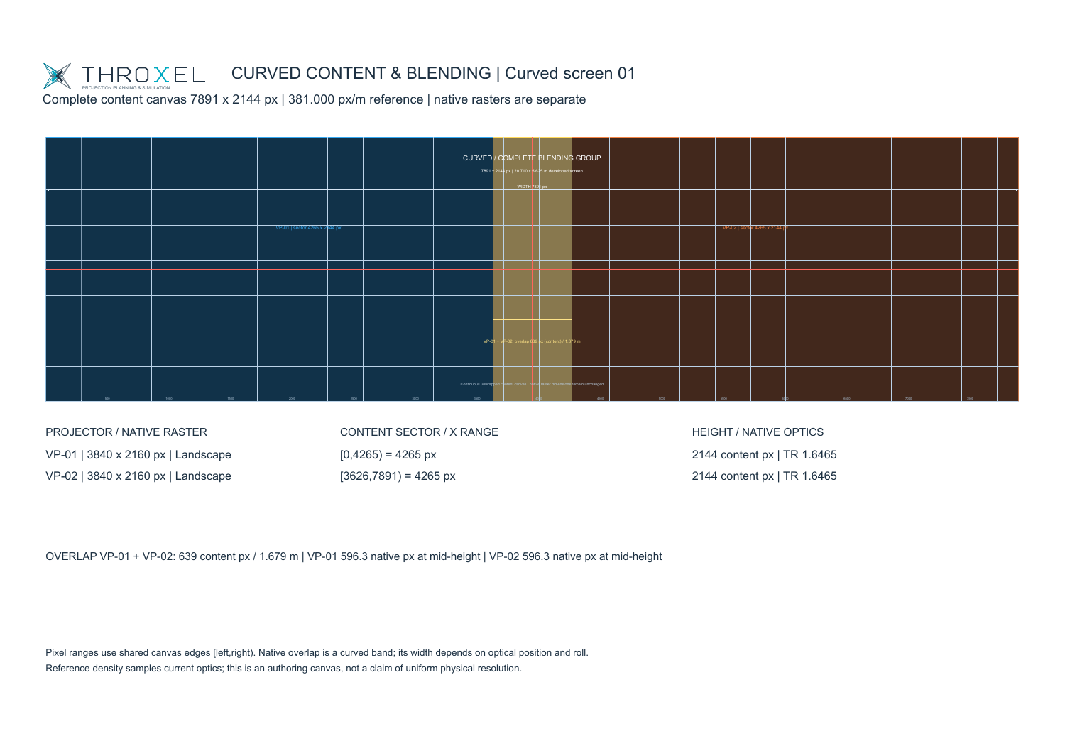
EXPORTED FROM THROXEL
Two projectors. One curved screen. Explore the optical layout, physical dimensions and unwrapped blending canvas in an actual THROXEL technical export.
SCENES & REFERENCES
Connect the projection design to the space where it will be installed, using 3D geometry and the reference documents supplied by the production team.
Bring external 3D geometry into the scene to provide context for screens and projector positions. Model preparation and material compatibility depend on the import route and source file.
Material and texture handling is an area of ongoing improvement.
Use images, PDF documents and CAD drawings as scaled references in plan and elevation. Align the venue drawing with the 3D scene and manage reference visibility and layers.
Planned formats include PNG/JPG, PDF and DXF. Direct DWG, DWF and Vectorworks (.vwx) support is under evaluation, not currently confirmed.
Mark two points on a reference, enter the real distance between them and scale the reference to match. Use known dimensions to place screens, walls and projectors in context.
WORKSPACE MODES · PLANNED
A dedicated reference workflow is planned to keep venue information separate from the objects you are actively designing.
Import, position, rotate and calibrate drawings and reference models. Manage their layers and align them with your installation.
Keep reference transforms locked while you work on screens, projectors and scene objects. Adjust reference opacity or visibility without moving the underlying plan.
This Reference / Installation workflow is planned for a future version. The intended startup view is Work Mode with the Installation tab open.
ENVIRONMENT & VIEWPORT QUALITY
Keep the same project at the centre of the workflow, from practical checks at the venue to a polished visual presentation for the client.
Use climate controls and lighting presets to explore the visual environment around your installation. Set the scene for technical review or a client presentation.
Visual environment presets provide context. Photometric assessment still depends on the equipment, surfaces and measured ambient conditions.
THROXEL reads the available hardware to recommend an appropriate viewport quality profile. Use Laptop or Performance settings for practical on-site work, with manual control when you need it.
Visual quality settings adapt rendering workload; they do not change the underlying projection calculations.
Back at the office, use a capable workstation and Cinematic quality to prepare richer views of the installation. Compose the scene and export captures for the client alongside the technical documentation.
Rendering performance depends on the hardware and the complexity of the scene.
04 / BUILT FOR AV PRODUCTION
THROXEL supports the planning, simulation and validation stage of an audiovisual production. It complements your media-server workflow; content playback and show control remain with your media server.
It describes a proposed projection installation. Contact the person who sent it for the project-specific values, equipment and installation conditions.
THROXEL
Private beta · Windows
Developed around real projection projects and the people who deliver them.
Public download is not yet available.